

Thread roller monitoring is usually done with force sensors in the machine frame, the die block or in bolster pieces in front of the setting screws. However, a gap in monitoring of thread rollers exists, if the rolling forces are very low (small or very short screws) or if it’s a re-rolling process after hardening.
This situation occurs especially on small thread rollers for micro screws or on bigger machines, which re-roll threads after hardening of the part.
For those applications with low or erratic force signals, improved monitoring methods based on a distance measurement between an analogue distance sensor and the head of the screw, during the rolling process, was developed so that the main process failures are detectable.
The monitoring method (envelope monitoring) and the monitoring units (Brankamp X series) are the same as they are for force monitoring, but the type of sensor, sensor location, signal signature and set-up procedure are different. It is also possible to combine force and distance monitoring in one unit, so both types of process signal can be evaluated inside the Brankamp system.
A lot of rolling failures are caused by a poor introduction process of the part, so in those cases, the part can raise, run down, slide during the rolling process or be introduced at a wrong level. In cases where the part is rolled with a washer, a missing washer can cause the same process failure as the introduction at a wrong level.
All these failures can cause a variation of the distance between a distance sensor, which is mounted above the rolling dies and the head of the part when it is passing the sensor position.
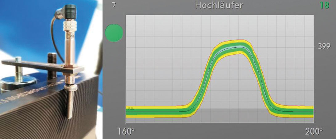
If the part runs up, the distance reduces and if the parts runs down, the signal increases. In all cases, whether the part slides or gets stuck during the introduction or rolling process, the timing of the distance curve varies and exceeds the envelope, which is expecting a reproducible timing of the rolling process.
An additional help to adjust the sensor is a led indicator on the sensor itself, which shows the operator that the distance between the head of the screw and the sensor is inside the measurement range. If the adjustment is correct, it leads to process signals to inform the operator.


Having spent a decade in the fastener industry experiencing every facet – from steel mills, fastener manufacturers, wholesalers, distributors, as well as machinery builders and plating + coating companies, Claire has developed an in-depth knowledge of all things fasteners.
Alongside visiting numerous companies, exhibitions and conferences around the world, Claire has also interviewed high profile figures – focusing on key topics impacting the sector and making sure readers stay up to date with the latest developments within the industry.

Don't have an account? Sign Up
Signing up to Fastener + Fixing Magazine enables you to manage your account details.